Peltier Cooled 300D Camera with Filter Removal and Amp Off Modification
Please note the URL change: This information was moved from glogg.jupiter-io.net/300d to chroic.wordpress.com on 8/22/2016.
Here is the obligatory info: I take no responsibility for any damage one may do to their cameras by using the information contained on this site. It is important of course to realize that you will void the warranty of your camera by partaking in any of these mods. All information on this site is copyright (c) Mike Kudenov 2006 unless otherwise noted, and may not be directly utilized for profit without permission. Now, on to the mods…
8/31/09: This weekend I was fortunate enough to find some time to continue work on the 350D mod. I added a peltier cooler with a cold finger assembly to the camera, similar (conceptually) to a commercial unit I saw a while ago – though it does not have many (if any) dew/condensation prevention features yet. Ultimately, not the most efficient way to transfer the energy – but it works. In any case, here are some darkframes from the system as it stands,
Darkframe – 15 Minutes, ISO1600, 40F (Amp-off circuit disabled)
Darkframe – 15 Minutes, ISO1600, 40F (Amp-off circuit enabled)
I anticipate that the sensor is close to 40F. Note that before, the refrigerator was at 40F, so the previous darkframes probably had a sensor temperature higher than that. These frames were processed from Raw in Iris, then saved to a bmp before compression as a jpg in photoshop. I’ll post some raw data once I get the amp-off circuit soldered to a prefboard. Currently, some extra noise, in the form of horizontal lines, are present within the amp-off image. This is likely due to the proximity of the power supply/peltier to the breadboard/amp-off circuit. I am anticipating it will vanish when everything is soldered up.
Here are some photos of the cooling. It’s definitely a quick and dirty job, since I’ve only spent about a day or two on it.


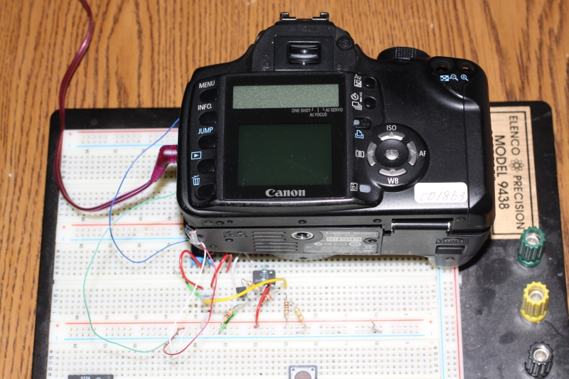
6/23/09: It has been a while since I last updated anything here, but recently I have attempted to modify the Canon 350D Digital Rebel with a similar amp-off modification. Currently, the circuit is on a breadboard connected to the sensor via. leads, as depicted below. Placing the whole setup in my refrigerator (~ 40 F or 4.4 C) yielded the following darkframes:
Darkframe – 20 Minutes, ISO1600, 40F (Amp-off circuit disabled)
Darkframe – 20 Minutes, ISO1600, 40F (Amp-off circuit enabled)
These are preliminary results. I won’t have final results until I can cool the sensor independent of my refrigerator. Also, I want to mention that I have other photos posted that I have taken with the 300D on my main site. More to come.
11/6/07: Some more pics I took last weekend and a few weeks ago with the camera and the R200SS: Orion nebula, Andromeda, Pleiades, Comet Holmes, Pelican. The pelican nebula could have come out better, but there were temperamental clouds that night which limited the exposure time to an hour.
5/31/07: Here are some shots of the lagoon nebula and the trifid nebula taken from Las Cinnegas (about 40 miles south east of Tucson) a few weeks ago. 10 minute exposures on a Vixen R200SS 8” F/4 at ISO800.
1/15/07: Here are two more photos taken this weekend; more h-alpha shots taken with the modified camera on the ED80. First is the horsehead. It’s a stack of about 4 30 minute ISO800 exposures with some averaging done between them: Horsehead. The next is the Rosette Nebula and is composed of two 30 minute and one 45 minute ISO800 shot: Rosette.
1/9/07: I just recently received word from Filip Lolic of his implementation of the amp-off circuit using SMD devices; very compact. Additionally, I have another image I took just this weekend I wanted to share. It’s Orion again, but this time with a Baader 7 nm h-alpha filter (from alpine astro) using the modified 300D on an ED80. The outer region is ISO1600 at 45 minutes, then the exposure decreases as one approaches the core. It can be seen here. This image is fairly raw. I only used curves and never got around to doing any darkframe subtractions on it.
10/24/06: Over the last month, I’ve been able to get some more data (e.g. real results). I’ve used both my MK66 and my Orion ED80 on a variety of objects. Below are some un-processed images taken in light polluted skies with no LPS filter. These are full sized PNG’s. The first two have tracking error because my guidescope was way misaligned before I realized it, but the rest are fine.
Dumbell, 20 minutes, ISO800: MK66 6” @ F/12 (prime)
M33, 20 minutes, ISO800: MK66 6” @ F/12 (prime)
Orion Nebula, 15 minutes, ISO800: MK66 6” @ F/12 (prime)
Horsehead, 15 minutes, ISO800: ED80 3.1” @ F/7.5 (prime)
M45, 10 minutes, ISO1600: ED80 3.1” @ F/7.5 (prime)
Orion Nebula, 15 minutes, ISO800: ED80 3.1” @ F/7.5 (prime)
Viel, 10 minutes, ISO1600: ED80 3.1” @ F/7.5 (prime)
So far I’ve noticed that by not shielding the cables at all, an improvement in performance can be realized. Not sure why this is, but putting the shielding around those extension cables causes this weird fixed- pattern noise. Ultimately, it’s hard to see any electronic interference in the images even with them unshielded, and the performance is on-par (for short exposures of course :D) with that of an unmodified 10D. Hence I’m calling this camera done, as I’m very excited about the performance! Additionally, the Orion ED80 is a fantastic little scope — highly recommended. Also, I think the IDAS filter does help, especially when comparing the dumbell shot at ISO800 here without it to the dumbell I obtained previously below with the IDAS filter at ISO1600. In any case, the above exposures just go to show that the thermal noise is not present and the ampglow is absent.
Also here is one of the post processed pics from the ED80 Orion nebula shot. I averaged 3 15 minute exposures and a 7 minute for the core area, so it amounts to essentially a 15 minute exposure time wise. I didn’t use any dark frame subtraction for this particular shot. Orion nebula, 15 min, post processed.
9/26/06: Here are the measurements I obtained while probing the CMOS sensor. Some have asked so here it is. Just simple voltage measurements taken with a DMM. This simple datasheet for the 704F can be downloaded here. Please be aware that all the data in the “notes” column is just my best guess and may be completely incorrect. Additionally none of my notes on the rough transient response are included, but I may add those at a later time. Ultimately it’d be best to get o-scope readings, but I never had to go that far to get where I wanted with this mod.
Back in March I set out something I’ve wanted to do for quite some time: modify a digital SLR in a way that’d make it a dedicated camera for astrophotography. I’m not going to go through a lot of disassembly details here (other sites go through disassembly, of particular note is Gary Honis’ site), but I do plan to post as many results as possible.
First, I wanted to remove the IR blocking filter from the camera, as many others have already done. This increases significantly the effective responsivity of the camera to the H-alpha wavelength. Once I removed this filter, I measured its spectral response on a spectrometer I have access to at work, which yielded the following results,

For the above data I was forced to utilize an incandescent lightbulb as a reference. Unfortunately, these bulbs have lower output in the blues / UV than other sources, hence the reason for the lower SNR near these wavelengths. However, it at least provides a reasonably accurate quantitative description. As can be seen, the filter offers about 25% transmission near the H-alpha wavelength (~656 nm) and cuts off very smoothly starting from 550 NM out to 675 NM
The next issue I wanted to address is the thermal noise associated with long exposures. This requires a cooling system, and in hindsight it appears I went a bit overboard on mine, since I was coming from the grounds of CPU processor cooling with peltiers. To see pictures of the original design with its enormously oversized heatsink, check below:

In this design, the cmos sensor is mounted out infront inside a cold chamber that contains desiccant. Otherwise, it is at the same pressure as the outside atmosphere. As long as one doesn’t change elevation too severely, this configuration works very nicely to keep the moisture out.
From this, while it was obvious that the heatsink was doing its job (as can be seen, ice is present on the coldplate in the images) it was way overbuilt and extremely heavy for what was necessary. Furthermore, I wanted to get rid of the small flex connectors that can be seen inbetween the two cables, which meant making the heatsink a little shorter. Doing this yields the current design (9/10/06), which can be seen below,

Now, as can be seen above, the cables are contiguous until they arrive inside the cmos’ chamber (using 8 inch long flex cables, Digikey part #WM10245-ND). There is one male to male flex adapter (as is discussed in the resources section) present inside the chamber in the front. Shielding on this cable uses a copper tape purchased from Digikey (part # 3M1181B-ND) along with aluminum foil, insulated with electrical tape. Shielding these cables is very crucial and their connection to ground must be firm and their physical stability must be high (they can’t be allowed to move significantly when prodded), or noise may be present on the final image. So far, from the testing I have done, this configuration proves more effective than my previous one (where I had two flex cables of differing length connected by an additional male-to-male flex adapter). While the previous configuration allowed a better selection of lengths, the additional flex adapter caused problems that were non-periodic and hard to pin down.
The last issue I wanted to address with this mod was that of the amplifier. It turns out that when one cools the CMOS chip, the amplifier noise becomes much worse. This is likely due to biasing inside the sensor changing with temperature, making the internal amp-off circuitry behave less effectively. This is just my best guess from all of my experimentation with the chip, and it may be incorrect. In any case, the bottom line is with the amp off, I can extend exposures out to one hour without significant issues.
For instance, here is a 15 minute ISO1600 default 300D uncooled darkframe (from the cmos sensor mounted in the chamber, but the peltier turned off) and a 15 minute ISO1600 default 300D cooled darkframe. The cooled darkframe has less thermal noise, but more amplifier noise, than the uncooled one. However, with the amp off mod enabled the difference is quite noticeable. Here is a 15 minute ISO1600 amp-off mod 300D uncooled darkframe and finally a 15 minute ISO1600 amp-off mod 300D cooled darkframe. With the amp off mod, the amplifier noise is difficult to spot without inverting the colors in the frame.
Ultimately, even with my previous setup with the additional flex adapter, I was able to obtain these images off my telescope before the monsoon season started. These are unprocessed pics. They are unprocessed to demonstrate the (what I consider low) noise levels more clearly.
M27, 20 minutes, ISO1600, below freezing, amp off. IDAS LPs filter, MK66 at F/12, unprocessed (some tacking error but not horrendous).
M101, 30 minutes, ISO1600, below freezing, amp off. IDAS LPs filter, MK66 at F/12 unprocessed (tracking is poor on this one, leading to poor contrast in the object. There’s also an internal reflection in the lower right, but it shows that 30 min exposures and probably longer are easily possible).
The air temperature at the time was 80 degrees F. The CMOS sensor was around 20 – 25 degrees F.
Finally, here is a set of new 15 minute cooled darkframes taken with an air temp of 78 degrees, cmos temp at around 28 degrees F. These were taken using the single pin amp off mod per the circuit in the amp-off mod section; hence, it appears that the previously aforementioned column defect is not present despite the single pin switching. Rather, as was mentioned before, the error was being caused by a cable grounding issue that has since been resolved by utilizing a single contiguous cable and different grounding techniques.
300D, 28F, ISO1600, 15 MIN_1 Dark (5.8 MB)
300D, 28F, ISO1600, 15 MIN_2 Dark (5.8 MB)
300D, 28F, ISO1600, 2 SEC Dark (5.6 MB)
10D, Room Temp, ISO1600, 1 SEC Dark (5.6 MB)
Finally, here’s a picture of the camera mounted on my MK66. Reducing its size from previously by making the heatsink smaller has vastly improved the handling performance on the mount. In the next few days (hopefully by sept 15th) the monsoons will be over, and I’ll finally be able to get some solid clear skies for which to test this system out more thoroughly.

Camera Modification
As always, when embarking on any wild modification such as this, be sure you know what you’re getting yourself into, and that you could easily damage your camera in the process. I’ve personally been pretty brazen with my CMOS sensor, and it’s held out fine, but of course be sure to keep yourself continuously grounded to avoid that mysterious “it doesn’t work and I don’t remember doing anything bad” dilemma. And of course I will reiterate: I am not responsible for anything you do to your own system. All I know is that this mod worked for me, and it should “technically” work with any other canon camera using a 704F CMOS imaging sensor. There is even a strong possibility that it could even be extended to the newer 20D/350D or 30D.
In any case, here is where I’ll discuss a little about the amp off modification I implemented on my 300D. It may not seem overwhelmingly necessary, as the amp noise isn’t really all that terrible. However, as I said before, if the CMOS sensor is cooled to around 28 degrees F or lower (approximately), the amp glow becomes increasingly obtuse. I am not sure of the cause for this; all I knew at the time was if I wanted it to go away, I had to find another means of turning off the amp circuit. It turns out that this really isn’t terribly difficult to do on this camera, although it did take a lot of time to nail down. Ultimately, it turns out that no external timing devices are required for this amp-off circuit (eg timers, microcontrollers, or other circuits that could synchronize the amp-off circuit with the current exposure). This is because the 300D already has a way of disabling the onboard amplifier during an exposure, which is one reason why it fairs much better than the comparable offerings from Nikon, which lack this feature (although I’m not sure about recent Nikon DSLR’s). Hence, it is possible to tap into this already existing signal to trigger the tertiary amp-off circuit that I present here.
The circuit I have developed was done with components I had lying around. Therefore some of the components may not have been the most ideal for the task at hand. In any case, here is the amp-off circuit schematic. The circuit above consists of seven resistors and three transistors, and can be divided into 3 stages. This first stage consists of the NTE2985, R1, R2, and R4. It is used for impedance matching purposes between the rest of the circuit and the 300D’s amp off signal (located at Pin 27B). This first stage switches the biasing for the second stage, which uses a 123AP or 2N2222 NPN BJT in conjunction with resistors R3, R6, and R7. This second stage is used to bias the third stage, which uses a 2N3906 PNP BJT wired in parallel with a ~630 ohm resistance to provide a reduction to the CMOS sensor’s voltage supply during an exposure. Basically you need to chose a resistance for R5 to give you approximately 3.7 V at the CMOS-side node during an exposure, and about 4.9 V to 5 V at readout. I’m not really going to go into much more detail than this, as the circuit is pretty self explanatory. It’s very similar to Steve Chamber’s original Toucam amp-off modification, except this one limits the source as opposed to the ground (ultimately the same thing). The only problem is there’s about two billion ground connections on the 300D’s CMOS sensor, and four connections to a +5V source, so it makes the latter easier to deal with. Additionally, I realize that there are more sophisticated amp-off mods that have been developed since then (using say, zener diodes), but this one is relatively straight forward and simple to implement on a sensor you have no datasheet for (or at least a datasheet you made yourself from meticulous probing).
In any case, I want to mention a bit about this MOSFET before going on with the rest of it. The NTE2985 is not necessarily the most ideal component to use in this circumstance, considering its size,

However, any similar N-channel enhancement mode digital (5V Vgss) MOSFET should work, but if you use a different transistor, I’d double check that a +3V signal at the gate will cause saturation of the device (e.g. if you place a 1k resistor between the drain and +5V, and connect the source to ground, then apply +3V through the 470K resistor at the gate, then you should read close to 0V across the transistor (Vds). If not, a different transistor is in order, or different biasing may be required). But I’d imagine that any digital MOSFET should be able to achieve this assuming the designers are aiming for a threshold voltage of around 1.5V.
Now for the pin locations. To make this circuit work you need to connect to the pins indicated in the following pictures, (click for a larger versions)

View of the backside, top region of the chip

View of the backside, bottom region of the chip
As can be seen, there are 4 connections to be made. Out of these, one pin must be lifted to allow one to connect a wire to the CMOS side and CAM side of the system. Furthermore, 3 additional pins must be disconnected. These are the additional voltage source pins (as said previously, there are 4 total). I tested fairly rigorously and did not notice any qualitative difference in image quality when I disconnected these 3 pins; they all appear to be connected to the same node, so I found no issues with it. However, it is completely possible to switch all 4 nodes simultaneously if one discovers a problem with it.
Ultimately, I only lifted one of the pins. They are very strong pins, and it was difficult to get even one of them lifted enough to fully disconnect it from the pad (just solder sucking will not disconnect the pin). So I decided to disconnect the other 3 voltage source pins by cutting into my flex cable with a razor blade. I simply removed a small portion around the lead that connected the voltage source to the camera. This way I have the option of disabling the mod by switching a cable, but I don’t see myself doing that in the near future 🙂
Resources
Here is a brief list of resources that I used in building my camera, including vendors and places to get some of the parts from (specifically the machining and the flex cables). For the machining, I found an online place at emachineshop.com. They have their own CAD software that you can use for free. It will provide 3D renderings of the part, and it will enable you to get real-time quotes for any of your ideas. Lead-times usually vary from 25 – 30 business days, but considering the quality of the work they do, I feel it’s well worth it. It did range a bit on the pricey side (expect single parts to run around $150-$250 average), but without your own access to a milling machine or similar, and with a desire to do it the right way the first time, there really aren’t many other alternatives.
While I did use a different CAD program to design the main cooling assembly, I was able to figure out their software fairly quickly. You do need to use their software, as they will not accept any other CAD formats, but I didn’t find this to be a problem at all. Another outfit that I found useful for my reverse engineering of the sensor for the amp off mod is also run by the same place. It’s located at pad2pad.com. From these guys, I used their CAD software to design a basic surface mount flex adapter so I could tap into the wires more easily to monitor voltages and currents, and to disconnect and reconnect the wires to a breadboard.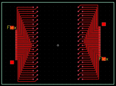 This ran me about $85 for 10 boards (1 board cost $80, so it was a quantity discount) and they ended up sending me 16 boards. Way more than I needed, but if you wanted to say, make a small surface mount PCB for the amp off mod so you could insert the circuit into the default housing of the 300D, then this would be one good way to do it. Lead-times run around 10-12 days, and again you must use their CAD software to design and submit orders.
Lastly, the flex connectors. I ordered these from DigiKey. The connectors on the CMOS sensor have 32 pins, but the flex cables they have at DigiKey are 36 pins, so I ordered several 36 pin ribbons and connectors. You just have to keep yourself aware which side you are connecting the CMOS sensor’s ribbons to. This is, of course, only if you are thinking about mounting the imaging sensor elsewhere. You’ll also have to cut off 4 of the pins from one of the ribbons when you connect it to the camera (where the cmos sensor used to be), and there is some meticulous soldering required to connect two of the 36 pin flex connectors together end to end (the best way I found how to do it). To clarify this, check out these pictures of the ribbons and connectors here. They are fairly simple to solder together end to end once you’ve made their initial alignment. The key is to NOT use extra solder (there is already solder on the pins that will bind them) and to use solder flux. This being said, it is extremely extremely extremely important that these connectors be cleaned very thoroughly before they are epoxied. I found that the flux tended to create a high resistance connection between some of the pins, and this caused problems with my first batch of connectors. Just make sure you are anal about checking for shorts or high resistance connections between adjacent pins on the flex connectors before gluing them if you decide to go with this method. Also, they are very fragile up until they are epoxied, and it’s not worth even trying to test them until they have glue between them. Hot glue might work as a temporary test, however, I have not tried this, and removing the hot glue to replace it with epoxy would probably break it apart, causing you to start all over again.
Anyways, the part numbers from digikey for the flex cables/connectors are,
HFJ36CT-ND (surface mount flex socket, 36 pins) You need 2 of these per connector. They must be mounted end-to-end.
HFF-36U-06-ND (6” long 36 pin flex cable)
HFF-36U-04-ND (4” long 36 pin flex cable)
HFF-36U-03-ND (3” long 36 pin flex cable)
HFF-36U-02-ND (2” long 36 pin flex cable)
Contents (c) 2006 Mike Kudenov unless otherwise noted and may not be used for commercial purposes for profit without consent.

You must be logged in to post a comment.